Welcome to part 3 of the VCF-9.1 home lab series. The previous post in this series discussed the VCF 9.1 high-level design and lab best practices. In this post, I will discuss the planning and preparation for deploying a VCF 9.1 fleet.
After you have understood the VCF deployment models and the design is ready in your mind, the next step is to get familiar with the VCF Planning and Preparation Workbook. If you have been working on the VCF platform for quite some time, you already understand the importance of this workbook. The workbook is an Excel file that helps you gather the inputs required for deploying a VCF fleet. The v9.1 workbook can be downloaded from here
The VCF Installer is a ruthless validator. Before it deploys a single component, it checks DNS resolution, NTP reachability, NIC speed, disk eligibility, and IP availability. If any of those checks fail, bring-up stops. Unlike older VCF versions, where you could work around prerequisite gaps during installation, VCF 9.x Installer enforces its pre-checks as hard gates.
That means your hardware, network, DNS, and IP planning must be complete — and verified — before attempting deployment.
Hardware Requirement
Choosing Your Deployment Model
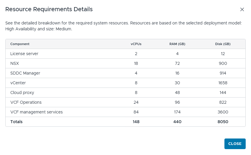
With VCF 9.1, the management domain footprint has become heavy as new components are added to the architecture. During deployment, you’re asked whether to deploy a simple topology or a highly available one. Also, you are asked for the size of the components. Your choice here directly determines your minimum host count and CPU/memory requirements. For a medium-sized, highly available deployment, the resource requirements are shown below.
Unsupported CPU
If your physical host has an unsupported CPU, you can bypass it by adding the allowLegacyCPU flag during the ESXi installation.
In my lab, I am using an HP DL380 Gen9 host with the following configuration:
- Memory: 512 GB
- CPU: 72 (with hyperthreading)
- Storage: 30 TB FC (Pure Flash)
- NIC: 2 x 25 GBPS

Pre-Deployment Planning
Documentation
The most common cause of failed VCF deployment isn’t misconfigured software — it’s under-planned infrastructure. Missing DNS records, incorrect MTU values, overlapping IP ranges, and absent reverse lookup zones all surface as cryptic installer failures that take hours to diagnose.
The VCF installer collects a significant amount of information during the bring-up wizard—FQDNs, IP addresses, VLAN IDs, DNS server addresses, NTP server addresses, and more. If you don’t have this information documented and verified before you start, you will either make mistakes mid-wizard or need to restart the bring-up process.
Build a planning document—even a simple spreadsheet that captures the requirements. The time investment is 2–3 hours, and it directly determines whether your deployment succeeds on the first attempt.
DNS Planning
DNS is the single most common bring-up failure point. Every VCF component requires a fully qualified domain name with both forward (A) and reverse (PTR) records resolvable before bringup starts. Choose a dedicated DNS domain for your lab. Use a private lab domain that does not conflict with your home network. Your DNS server must be located outside the environment/host where VCF 9.1 will be deployed.
In my lab, I am using Microsoft Server 2022 as a DNS server and have the DNS zone thinkon.lab configured.
IP Address Planning
Plan your IP space by function (traffic type), not by host. Each traffic type gets its own subnet and VLAN. This is not over-engineering—it’s the production pattern, and it matters because VCF’s deployment wizard asks for these ranges. I am using the following networks/VLANs in my lab:
| Network Type | VLAN | CIDR | Gateway | Purpose |
| VCF Management | 256 | 10.252.1.0/24 | 10.252.1.254 | ESXi Management network |
| VM Management | 80 | 10.252.80.0/24 | 10.252.80.254 | Infra Management VMs |
| VCF vMotion | 9 | 10.252.9.0/24 | 10.252.9.254 | vMotion network |
| VCF vSAN | 10 | 10.252.10.0/24 | 10.252.10.254 | vSAN Network |
| ESX TEP | 91 | 10.252.91.0/24 | 10.252.91.254 | ESXi TEP Network |
| Edge TEP | 92 | 10.252.92.0/24 | 10.252.92.254 | Edge TEP Network |
Transport Node TEP Details
| Transport Node | CIDR | IP Pool | Description |
| Mgmt Dom Host | 10.252.91.0/24 | 10.252.91.220 – 10.252.91.240 | Mgmt Domain ESX TEP |
| Mgmt Dom Edge | 10.252.92.0/24 | 10.252.92.209 – 10.252.92.224 | Mgmt Domain Edge TEP |
| WLD Dom Host | 10.252.91.0/24 | 10.252.91.171 – 10.252.91.180 | WLD Domain ESX TEP |
| WLD Dom Edge | 10.252.92.0/24 | 10.252.92.225 – 10.252.92.236 | WLD Domain Edge TEP |
I have intentionally omitted the BGP details, as I will cover that in the network connectivity setup post.
IP Allocation
To build the VCF management domain, the IP requirements are shown below:
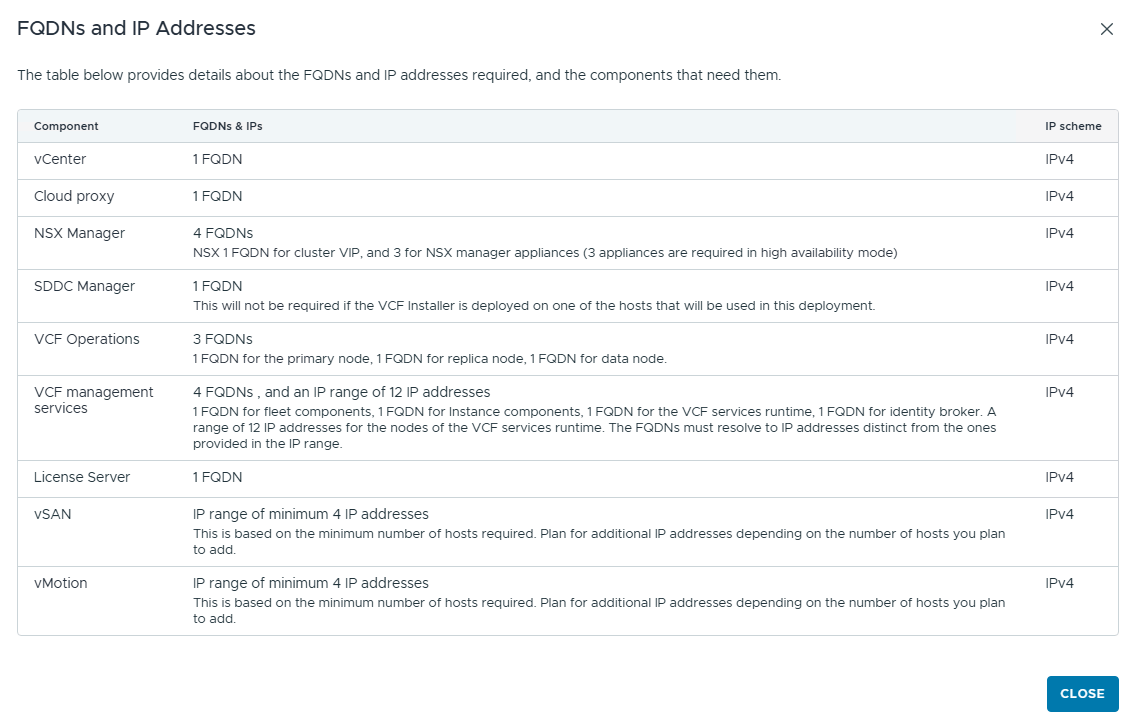
For the full list of IP/FQDN requirements, see VCF Components FQDNs and IP addresses
I have built my lab as per the IP/FQDN scheme shown in the table below. I have broken it down into day-0, day-1, and day-2 requirements.
Day-0 (Management Domain)
| Hostname/FQDN | IP Address | Component |
| vcf910-installer.cmb1.thinkon.lab | 10.252.80.35 | VCF Installer |
| vcf910-vcsa.cmb1.thinkon.lab | 10.252.80.36 | vCenter Server |
| vcf910-nsx.cmb1.thinkon.lab | 10.252.80.37 | NSX VIP |
| vcf910-nsx01.cmb1.thinkon.lab | 10.252.80.38 | NSX Node01 |
| vcf910-nsx02.cmb1.thinkon.lab | 10.252.80.39 | NSX Node02 |
| vcf910-nsx03.cmb1.thinkon.lab | 10.252.80.40 | NSX Node03 |
| vcf910-sddcm.cmb1.thinkon.lab | 10.252.80.41 | SDDC Manager |
| vcf910-fleetm.cmb1.thinkon.lab | 10.252.80.42 | Fleet Manager |
| vcf910-ops-clt.cmb1.thinkon.lab | 10.252.80.43 | VCF OPS Fleet Collector |
| vcf910-ops.cmb1.thinkon.lab | 10.252.80.44 | VCF OPS VIP |
| vcf910-ops01.cmb1.thinkon.lab | 10.252.80.45 | VCF Ops Mgr Node |
| vcf910-ops02.cmb1.thinkon.lab | 10.252.80.46 | VCF Ops Data Node |
| vcf910-ops03.cmb1.thinkon.lab | 10.252.80.47 | VCF Ops Replica Node |
| vcf910-lic-srv.cmb1.thinkon.lab | 10.252.80.51 | VCF License Server |
| vcf910-inst-mgr.cmb1.thinkon.lab | 10.252.80.52 | VCF Instance manager |
| vcf910-vidb.cmb1.thinkon.lab | 10.252.80.53 | VCF VIDB |
| vcf910-svc.cmb1.thinkon.lab | 10.252.80.54 | VCF Services Runtime FQDN |
| VCF VMSP Cluster | 10.252.80.160-10.252.80.179 | VCF Mgmt Services |
Note: For the VMSP cluster, a minimum of 12 IP addresses is required. A full range of 30 IPs is needed for components that can be deployed as day-N.
Note: If you are planning to deploy VCF Automation on day-0, you need additional IPs. I deployed VCF Automation on day-2.
Day 1: Workload Domain and NSx Edges
| Hostname/FQDN | IP Address | Component |
| vcf910-mgmt-edge01.cmb1.thinkon.lab | 10.252.80.48 | NSX Edge Node01 |
| vcf910-mgmt-edge02.cmb1.thinkon.lab | 10.252.80.49 | NSX Edge Node02 |
| vcf910-w01-vcsa.cmb1.thinkon.lab | 10.252.80.9 | WLD Dom VCSA |
| vcf910-w01-nsx.cmb1.thinkon.lab | 10.252.80.10 | WLD Dom NSX VIP |
| vcf910-w01-nsx01.cmb1.thinkon.lab | 10.252.80.55 | WLD Dom NSX Node01 |
| vcf910-w01-nsx02.cmb1.thinkon.lab | 10.252.80.56 | WLD Dom NSX Node02 |
| vcf910-w01-nsx03.cmb1.thinkon.lab | 10.252.80.57 | WLD Dom NSX Node03 |
| vcf910-w01-edge01.cmb1.thinkon.lab | 10.252.80.13 | WLD Dom Edge Node01 |
| vcf910-w01-edge02.cmb1.thinkon.lab | 10.252.80.14 | WLD Dom Edge Node02 |
Day 2: VCF Automation, Avi Controllers, DSM, etc.
| Hostname/FQDN | IP Address | Component |
| vcf910-vcfa.cmb1.thinkon.lab | 10.252.80.140 | VCF Automation VIP |
| vcf910-vcfa-svc.cmb1.thinkon.lab | 10.252.80.141 | VCF Automation SVC Runtime |
| VCF Automation SVC | 10.252.80.200/29 | VCF Automation SVC Cluster Nodes |
| vcf910-avi.cmb1.thinkon.lab | 10.252.80.86 | Avi VIP |
| vcf910-avi01.cmb1.thinkon.lab | 10.252.80.87 | AVI Node 01 |
| vcf910-avi02.cmb1.thinkon.lab | 10.252.80.88 | AVI Node 02 |
| vcf910-avi03.cmb1.thinkon.lab | 10.252.80.89 | AVI Node 03 |
| vcf910-dsm.cmb1.thinkon.lab | 10.252.80.21 | VCF Data Services Manager |
| vcf910-log.cmb1.thinkon.lab | 10.252.80.22 | VCF Log |
| vcf910-ni-platform.cmb1.thinkon.lab | 10.252.80.147 | Network Insight Platform |
| vcf910-ni-proxy.cmb1.thinkon.lab | 10.252.80.148 | Network Insight Collector |
Pre-Deployment Checklist
Run through this checklist completely before launching the VCF Installer. The installer will check most of these automatically, but catching failures here is faster than catching them mid-wizard.
Hardware
- Each host has ≥ 12 physical cores / 24 threads.
- Each host has ≥ 128 GB RAM.
- Hosts connected to the managed switch on trunk ports with all VLANs allowed.
Network / Switch
- All VLANs that will be used for the deployment are configured on the switch.
- Host ports are configured as trunks on the switch.
- Physical connectivity verified (link up on both NICs per host).
DNS
- A record was created for all components.
- PTR records are created for all IP addresses.
- The forward lookup returns the correct IP for every record.
- The reverse lookup returns the correct FQDN for every IP address.
NTP
- NTP server is running and reachable.
- NTP FQDN resolves from all hosts.
- Each ESX host is configured to sync to the lab NTP server.
- NTP is synchronized on each host.
ESX Host Preparation
- ESX 9.1 is installed on each host.
- SSH is enabled on each host.
- The management IP, subnet, and gateway are configured statically.
- DNS is configured on each host (pointing to the lab DNS server).
- Hostname set to FQDN.
- SSL certificate regenerated on each host. The host certificate shows it was issued to the host FQDN.
- NIC speed validation workaround applied if using non-10GbE NICs
VCF Installer Appliance
- VCF Installer OVA deployed on the infra host.
- VCF Installer VM has management network connectivity.
- VCF offline bundle downloaded and staged in depot (if not using online mode).
What’s Next
With hardware ordered, a planning document complete, and every item in the checklist verified, you’re ready to deploy the VCF fleet. Part 5 of this series will cover the VCF Installer walkthrough in detail—launching the bring-up wizard, validating the pre-checks, and watching the management domain come to life.
And that’s it for this post. In the next post of this series, I will discuss the VCF offline depot setup!!!